Blue electric brakes or hydraulic reverse disable see blue wire notes below in the trailer wiring diagram and connector application chart below use the first 5 pins and ignore the rest. Special light and wiring systems need to be installed on your tow vehicle before you can tow any trailer.
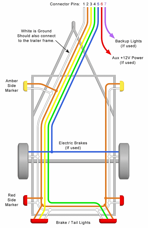
If the trailer wiring is running down the left side of the trailer then we splice the left side brake assemblies into the main electric brake power wire coming from the 7 way connector.

You can find out more Diagram below
Electric brake wire diagram. If your truck has a built in 7 pin socket but you only need 5 of the pins. Trailer wiring and brake control wiring. A wiring diagram is a straightforward visual representation of the physical links as well as physical design of an electrical system or circuit.
Break away systems may be added to the service brake circuit. Wiring diagram for utility trailer with electric brakes gallery collections of wiring diagram trailer electric brakes valid wiring diagram trailer. Electric brake controller wiring diagram.
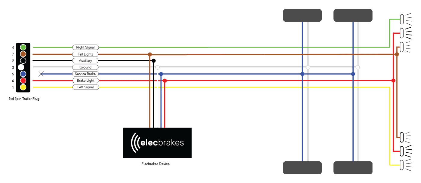
Redarc electric brakes wiring diagram best trailer brake wiring. Auxiliary connection is optional it may be connected to any 12v to 24v constant power source or left unconnected. It reveals the components of the circuit as streamlined shapes and also the power as well as signal links in between the tools.
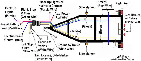
This vehicle is designed not just to travel one location to another but also to carry heavy loads. Various connectors are available from four to seven pins that allow for the transfer of power for the lighting as well as auxiliary functions such as an electric trailer brake controller backup lights or a 12v power supply for a winch or interior trailer lights. Wiring diagram trailer electric brakes inspirationa wiring diagram.
Use the 7 pin connector anyway see below and just leave out the last 2 wires. It demonstrates how the electrical cables are adjoined and can likewise show where fixtures and components may be linked to the system. A wiring diagram is a simplified traditional pictorial representation of an electrical circuit.
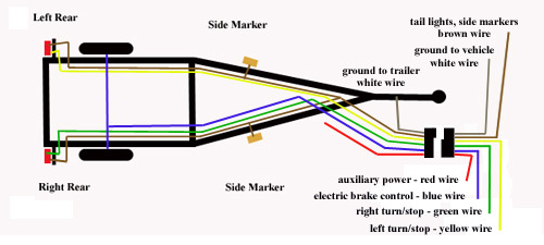
When as well as how you can utilize a wiring diagram. Wiring diagram trailer electric brakes best electric trailer brakes. Trailer wiring diagrams trailer wiring connectors various connectors are available from four to seven pins that allow for the transfer of power for the lighting as well as auxiliary functions such as an electric trailer brake controller backup lights or a 12v power supply for a winch or interior trailer lights.
Tail light converters brake control wiring vehicles towed behind a motorhome wiring diagram for common plugs breakaway switches. Elecbrakes is designed to operate 1 to 2 braked axles. We then run a jumper wire from the electric brake power wire to the right side brake assemblies see photo.
Reese trailer brake controller wiring diagram hayman reese trailer brake controller wiring diagram reese electric brake controller wiring diagram reese pilot trailer brake controller wiring diagram people today comprehend that trailer is a vehicle comprised of very complicated mechanisms.


0 comments:
Post a Comment